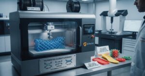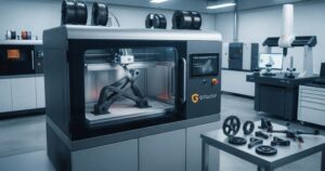
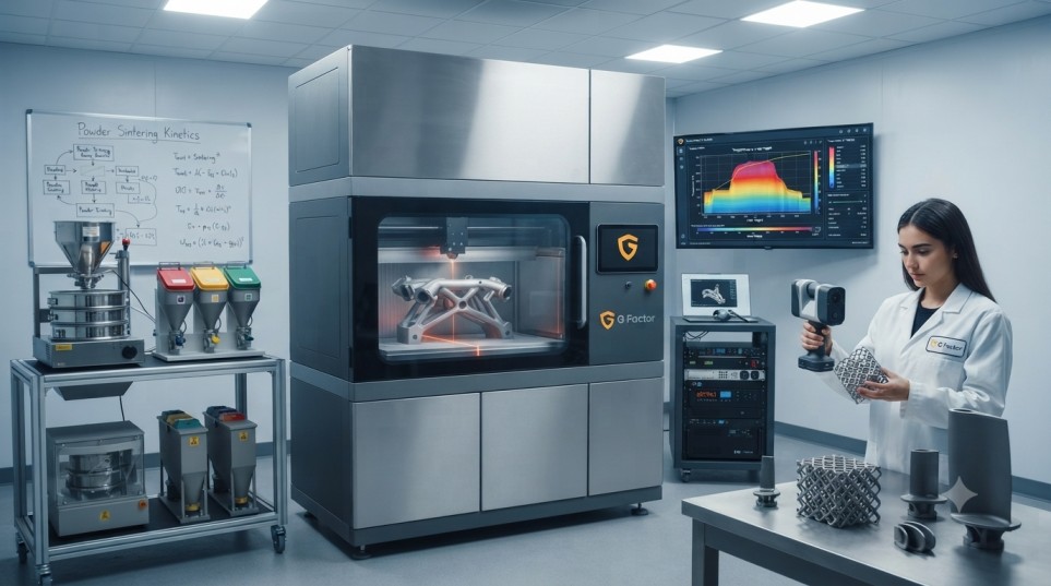
If you step onto a modern production floor in aerospace, automotive, or heavy industrial tooling today, you will notice a fundamental shift in how physical products are brought to life. For over a century, manufacturing relied almost entirely on cutting material away from a solid block of metal or plastic. Today, production lines are rapidly adopting a process that builds objects from the ground up, layer by single layer.
So, what is additive manufacturing? In simple terms, additive manufacturing explained simply is the industrial process of joining materials to make three-dimensional objects from 3D model data, usually layer upon layer, as opposed to traditional subtractive manufacturing methods.
Whether you call it 3D printing, direct digital manufacturing, or additive production, this technology is no longer just for rapid prototyping or desktop hobbies. It has transformed into a robust, high-throughput manufacturing pillar capable of producing end-use automotive body panels, lightweight aerospace brackets, custom medical orthotics, and complex architectural molds.
In this ultimate guide, we will break down additive manufacturing in plain English. We’ll look at how it works step by step, explore the key technologies driving shop floor adoption—including Fused Filament Fabrication (FFF) and ultra-fast Fused Granular Fabrication (FGF)—compare traditional subtractive methods with additive systems, examine real-world ROI, and give you a clear roadmap to implement this technology in your own operations.
What Is Additive Manufacturing? (The Simple Explanation)
To understand additive manufacturing without getting lost in technical jargon, think about baking a layered cake vs. carving a statue out of marble.
-
Subtractive Manufacturing (The Marble Statue): You start with a massive solid block of material (steel, aluminum, wood, or plastic) and use CNC mills, drills, and lathes to chip, slice, and carve away everything you don’t need until the final shape remains. You end up with a lot of wasted metal shavings and leftover material.
-
Additive Manufacturing (The Layered Cake): You start with nothing. A digital computer-aided design (CAD) file tells a machine exactly where to place material. The machine deposits ultra-thin layers of molten plastic, metal powder, or resin directly on top of each other until the complete, solid 3D part is finished.
Because you only place material exactly where the digital design calls for it, additive manufacturing eliminates massive material waste, allows for internal geometric shapes that traditional drill bits can’t physically reach, and removes the need for expensive upfront hard tooling.
How Additive Manufacturing Works: Step-by-Step
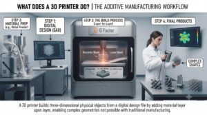
While additive manufacturing encompasses several distinct hardware processes, the fundamental digital-to-physical workflow remains consistent across virtually all systems. Here is how a digital concept becomes a physical part on the factory floor:
-
Digital Design (CAD): Everything begins inside a 3D Computer-Aided Design (CAD) environment. Engineers construct a digital representation of the part.
-
File Export (STL / OBJ / 3MF): The CAD model is converted into an additive-ready file format that breaks down the 3D surface into readable layer data.
-
Slicing Setup: Slicing software horizontally cuts the digital model into hundreds or thousands of flat cross-sections and outputs G-code toolpaths.
-
3D Printing: The machine executes the G-code instructions, depositing or fusing material layer by layer until the part is built.
-
Post-Processing: The finished part is removed for support structure cleaning, surface finishing, heat treatment, or secondary machining.
Step 1: Digital Design (CAD)
Everything begins inside a 3D Computer-Aided Design (CAD) environment. Engineers use software like SolidWorks, Autodesk Fusion 360, or Siemens NX to construct a digital representation of the part. Because additive processes aren’t constrained by traditional tooling paths, engineers can optimize geometries using generative design—creating organic, lattice-filled structures that are exceptionally strong yet lightweight.
Step 2: File Export (STL / OBJ / 3MF)
Once the design is finalized, the CAD model is converted into an additive-ready file format. The most common legacy format is an STL (Stereolithography) file, which breaks down the 3D surface into a mesh of tiny triangles. Modern workflows increasingly use 3MF files, which store material data, color specifications, and structural properties alongside the mesh geometry.
Step 3: Slicing and Toolpath Generation
The exported 3D file is imported into “slicing” software. The slicer horizontally cuts the digital model into hundreds or thousands of flat layer cross-sections based on user settings like layer height (e.g., 0.2 mm or 3.0 mm), nozzle diameter, print speed, and infill density. The software then outputs a G-code file—the exact machine language instructions that command the 3D printer’s motors, temperatures, and extruders.
Step 4: Machine Setup and Printing
The operator loads the feedstock—whether spooled filament, raw plastic pellets, or metal powder—into the machine. After executing automated bed-leveling routines and preheating thermal chambers, the printer begins the build sequence. Layer by layer, the printhead traces the G-code path, depositing or fusing material until the full vertical height is achieved.
Step 5: Post-Processing
After the build plate cools, the part is removed. Depending on the technology and application, post-processing can range from simple support structure removal and light sanding to CNC machining for critical sealing surfaces, heat treating, or chemical vapor smoothing for an injection-molded surface finish.
Key Additive Manufacturing Technologies Explained
Additive manufacturing isn’t just one single process—it’s an umbrella term covering several distinct ISO/ASTM categories. Let’s break down the most dominant industrial categories you will encounter.
1. Material Extrusion (FFF & FGF)
Material extrusion is the most widely adopted additive technology on the market today due to its versatility, affordability, and broad material support.
-
Fused Filament Fabrication (FFF): Spooled plastic wire (typically 1.75 mm or 2.85 mm diameter) is driven through a heated hotend, melted, and extruded through a fine nozzle. FFF excels at producing detailed, high-precision engineering parts, intricate enclosures, and functional jigs.
-
Fused Granular Fabrication (FGF / Pellet Extrusion): Instead of using expensive spooled filament, FGF printers feed raw, industrial plastic granules—the exact same bulk pellets used in injection molding—directly into a screw-driven hopper on the gantry. FGF offers massive throughput (up to 15+ kg/hr), allowing companies to print large molds, full-scale auto bumpers, and architectural panels at a fraction of the cost.
2. Powder Bed Fusion (SLS & DMLS/SLM)
Powder bed fusion uses a high-powered thermal energy source to selectively fuse powdered particles layer by layer.
-
Selective Laser Sintering (SLS): A CO2 laser traces cross-sections over a bed of thermoplastic powder (usually Nylon/PA12), sintering the grains together. Unfused powder supports the part during printing, eliminating the need for support structures.
-
Direct Metal Laser Sintering (DMLS) / Selective Laser Melting (SLM): Uses a precision fiber laser to melt metallic powders (titanium, aluminum, stainless steel, Inconel). This allows aerospace and medical firms to produce high-strength functional metal components.
3. Vat Photopolymerization (SLA & DLP)
Vat photopolymerization relies on light-curable liquid photopolymer resins.
-
Stereolithography (SLA): An ultraviolet (UV) laser traces across a vat of liquid resin, instantly curing and hardening the plastic layer by layer. SLA provides ultra-smooth surface finishes and microscopic feature accuracy, making it a favorite for dental models, jewelry patterns, and high-detail visual prototypes.
Deep Dive: FFF (Filament) vs. FGF (Pellet) Industrial Systems
For engineering and operations teams evaluating industrial plastic extrusion hardware, the debate almost always centers around FFF vs. FGF. Both technologies build parts additively, but their mechanical inputs, throughput capabilities, and part economics are vastly different.
To explore real-world hardware options across both categories, check out our dedicated catalog of FFF 3D Printers and explore heavy-duty, high-throughput FGF Pellet 3D Printers.
Fused Filament Fabrication (FFF)
FFF systems push material through a heated nozzle using motorized drive gears acting on solid filament.
-
Precision and Surface Detail: FFF shines when printing thin-walled enclosures, sharp internal corners, fine threads, and intricate mechanical features. Layer heights can be tuned down to 0.05 mm (50 microns).
-
Material Versatility: High-temperature FFF platforms like the GPEEK300 can process technical polymers like PEEK, PEI (Ultem), and Polycarbonate (PC) alongside carbon-fiber-reinforced wires.
-
Limitations: Deposition rates are relatively slow (typically 15 g/hr to 300 g/hr), making large parts over 1 meter long expensive and time-consuming to build.
Fused Granular Fabrication (FGF)
FGF hardware replaces the traditional filament feed mechanism with a heavy-duty, multi-zone heated screw extruder mounted directly on a rigid motion gantry.
-
Unmatched Output Speed: FGF nozzles range from 2.0 mm up to 16.0 mm, delivering material flow rates from 1,000 g/hr up to 15,000+ g/hr (15 kg/hr) on platforms like the JS-FGF-AM-2420. A job that takes 10 days on a filament printer can be finished in under 12 hours on a pellet platform.
-
Dramatic Material Cost Reduction: Raw plastic pellets cost 60% to 80% less per kilogram than processed filament spools. This makes full-scale manufacturing of large objects economically viable.
-
Hybrid Machining Integration: Massive FGF gantries like the JS-FGF-HM-3000 often incorporate secondary 3-axis CNC milling heads. The machine rapidly prints a near-net shape object, then automatically switches to the CNC spindle to mill critical mounting faces, bolt patterns, and sealing surfaces down to ±0.05 mm tolerances.
Detailed Comparison: Additive vs. Subtractive Manufacturing
To help your operations and procurement teams choose the right process, here is an in-depth operational comparison between additive manufacturing and traditional subtractive CNC machining:
| Operational Metric | Additive Manufacturing (3D Printing) | Subtractive Manufacturing (CNC Machining) |
| Primary Mechanism | Material deposited layer-by-layer | Material cut/carved away from a solid billet |
| Material Utilization / Waste | High efficiency (up to 90–95% material usage) | Low to moderate (often 40–80% scrap metal/plastic) |
| Geometric Complexity | Near-limitless (internal voids, lattices, organic forms) | Constrained by tool reach, angles, and axis paths |
| Tooling & Setup Requirements | Zero custom tooling; direct CAD-to-part workflow | Requires jigs, fixtures, custom tooling, and CAM paths |
| Initial Lead Time | Hours to days (rapid iteration) | Weeks to months (if hard tooling/fixtures are needed) |
| Unit Cost vs. Volume | Fixed cost per unit; ideal for low-to-mid volumes | High initial cost; ultra-low cost at massive volumes |
| Surface Finish | Visible layer lines (requires post-processing for optical smooth) | Superior raw surface finish (Ra < 0.8 µm out of the machine) |
| Best Suited For | Prototyping, custom tools, complex molds, low-volume production | High-volume standardized parts, simple prismatic shapes |
Industrial Materials: From Basic Polymers to High-Temp Composites
Your additive manufacturing machine is only as capable as the chemistry you feed into it. Modern industrial 3D printing has moved well beyond basic commodity plastics into advanced, structural materials. To learn more about available materials, explore our master guide to 3D Printing Materials.
1. Standard Polymers (Commodity & Prototyping)
-
PLA (Polylactic Acid): A bio-based polymer derived from cornstarch or sugarcane. It prints at low temperatures with near-zero thermal shrinkage, making it ideal for visual design proofs and early concept models.
-
ABS (Acrylonitrile Butadiene Styrene): A tough, impact-resistant thermoplastic widely used in consumer goods and automotive interiors. It requires an enclosed print chamber to prevent thermal warping.
-
PETG: Combines the ease of printing of PLA with the impact toughness and chemical resistance of ABS. Highly water-tight and UV-resistant.
2. Flexible Polymers
-
TPU (Thermoplastic Polyurethane): An elastomeric material offering rubber-like flexibility, high tear strength, and excellent shock absorption. Used extensively for custom gaskets, protective seals, flexible boots, and orthopedic cushioning.
3. Fiber-Reinforced Engineering Composites
By blending short carbon fibers or glass fibers into thermoplastic matrices, material scientists create composite feedstocks with incredible mechanical performance. Discover options in our catalog of FGF Pellet Materials and FFF Filament Materials.
-
PC+CF (Polycarbonate + Carbon Fiber): Carbon fibers dramatically increase structural stiffness and lower the thermal expansion coefficient. Ideal for high-strength jigs, fixtures, and vacuum forming molds.
-
PA+GF (Nylon + Glass Fiber): Offers remarkable fatigue resistance, chemical durability under harsh automotive hood environments, and high heat deflection.
-
PP+GF (Polypropylene + Glass Fiber): Lightweight, hydrophobic, and chemically inert. Preferred for fluid ducting, marine components, and outdoor architectural structures.
-
PLA-CF: Enhanced rigidity over standard PLA, offering a crisp matte surface finish and higher structural resistance for drone frames and lightweight fixtures.
4. High-Temperature Ultra-Polymers
-
PPS+CF & PESU+CF: Advanced technical polymers designed to survive continuous service temperatures exceeding 200°C. These high-performance plastics are increasingly used as direct metal replacements in aerospace ducting, motorsport components, and composite autoclave curing tools.
Real-World Applications Across Industries
Additive manufacturing has moved far beyond simple visual prototypes. Today, it actively drives production workflows across major sectors detailed in our 3D Printing Industries Overview. To see how these systems are implemented across different operations, learn more About GFac.
Automotive & Transportation
Automotive OEMs and tier-1 suppliers use large-scale FGF pellet systems like the JS-FGF-1800Pro and JS-FGF-AM-2420 for Automotive 3D Printing. They produce full-scale concept body panels, dashboard prototypes, and assembly line fixtures. Printing a 2-meter prototype bumper in-house takes under 30 hours using raw pellets, compared to 8+ weeks for traditional bridge tooling.
Aerospace & Composites
In Aerospace 3D Printing, every gram of weight saved directly translates to lifetime fuel efficiency. Engineers use additive systems to print topology-optimized brackets that eliminate unnecessary metal mass. Furthermore, high-temp composite materials are used to 3D print autoclave tooling that withstands heat and pressure during carbon fiber layup cycles.
Architecture, Public Art & Construction
Architects and construction teams leverage Architecture 3D Printing to print complex, custom formwork for Ultra-High-Performance Concrete (UHPC) casting. Instead of hand-carving expensive timber molds, large-scale pellet printers produce durable concrete molds in days. Similarly, in Sculpture 3D Printing, Furniture 3D Printing, and Display 3D Printing, creators use machines like the JS-FGF-1200 to turn digital art into massive outdoor monuments and custom interior designs.
Medical & Custom Orthotics
Additive manufacturing is inherently suited for custom, patient-matched medical devices through Medical 3D Printing. By combining 3D body scans with flexible TPU or durable PA materials, clinicians can print custom scoliosis braces, prosthetic sockets, and orthopedic insoles within 24 to 48 hours.
The Part Economics: Financial ROI Analysis (CapEx vs. OpEx)
When presenting an additive manufacturing proposal to management, demonstrating clear financial ROI is essential. Let’s compare the real-world operational costs of producing a 10 kg structural composite housing using industrial filament (FFF) versus industrial pellet (FGF) hardware.
Operational Cost Comparison
| Metric | Industrial FFF (Filament) | Industrial FGF (Pellet) |
| Feedstock Cost per kg | $50.00 / kg | $6.00 / kg |
| Material Cost (10 kg Part) | $500.00 | $60.00 |
| Deposition Time | ~50 Hours | ~4 Hours |
| Estimated Energy Cost | ~$25.00 | ~$12.00 |
| TOTAL DIRECT PART COST | $525.00 | $72.00 |
| COST SAVINGS PER PART | Baseline | 86.2% Cost Reduction |
Key ROI Takeaways
-
Feedstock Savings: If your facility consumes more than 300 kg of engineering plastic per year, the raw material cost savings offered by an FGF pellet system can pay back the hardware capital investment in under 6 to 12 months.
-
Lead Time Elimination: Eliminating third-party tooling lead times prevents costly downtime on assembly lines, saving thousands of dollars per day in operational overhead.
4-Step Selection Framework: Choosing the Right Additive System
To choose the best additive hardware for your factory floor, follow this four-step selection framework:
-
Map Your Build Envelope: Determine the physical dimensions of your largest expected components. If parts fit within a 1 m³ box, a compact industrial filament printer like the GM1000 1.75mm or GM1000 3.5mm keeps your machine footprint small. Medium builds benefit from systems like the G610 or G500pro. If you build parts over 1.5 to 3.5 meters, move directly to large gantry pellet systems like the JS-FGF-HM-2435.
-
Define Feature Tolerances: If your parts demand intricate internal channels, thin walls (<2 mm), or smooth raw cosmetics, choose FFF options like the G300 Pro or G220. If your goal is high structural volume, thick shell tooling, or large forms where light post-sanding or hybrid CNC milling is acceptable, choose FGF platforms such as the JS-FGF-800Pro.
-
Verify Thermal Capabilities: Match your required polymers to printer specs. Standard prototyping materials run under 300°C. Reinforced composites (PC+CF, PA+GF) require 350°C nozzles, while ultra-polymers (PEEK, PEI) demand high-temp capabilities and actively heated build chambers.
-
Audit Shop Floor Utilities: Ensure your facility has appropriate power and floor support. Compact FFF/FGF systems usually run on single-phase 220V AC power (3.0 kW to 4.6 kW). Large-scale industrial gantries like the JS-FGF-3000 require three-phase 380V AC hookups (45 kW to 85 kW) and reinforced concrete floors rated for weights up to 16,000 kg.
Frequently Asked Questions (FAQ)
What is additive manufacturing in simple terms?
Additive manufacturing is a process where 3D objects are created by depositing material layer on top of layer based on a digital 3D design file (CAD). It is the opposite of subtractive manufacturing, which cuts away material from a solid block. Have more questions? Check out our complete GFac FAQ Page.
Is 3D printing the same as additive manufacturing?
Yes, the terms are often used interchangeably. However, “3D printing” usually refers to smaller desktop or prototyping machines, while “additive manufacturing” is the broader industrial term for production-grade equipment used in end-use manufacturing.
What is the difference between FFF filament and FGF pellet 3D printing?
FFF uses solid spooled plastic wire pushed through a hotend, making it great for fine details and smaller parts. FGF feeds raw plastic pellets directly into a screw extruder, providing up to 10× to 100× faster print speeds and 60% to 80% lower material costs for large-scale parts.
What materials can be used in additive manufacturing?
Additive manufacturing supports a wide variety of materials, including commodity plastics (PLA, ABS), engineering composites (Nylon with carbon fiber, Polycarbonate), flexible elastomers (TPU), high-temp polymers (PEEK, PEI), and metals (titanium, stainless steel, aluminum).
How does additive manufacturing reduce material waste?
Subtractive manufacturing (like CNC machining) often cuts away 40% to 80% of a raw block as scrap shavings. Additive manufacturing deposits material only where required by the design file, resulting in up to 90% to 95% material utilization.
Summary Key Takeaways
-
Layer-by-Layer Production: Additive manufacturing builds parts from CAD data by adding material layer by layer, minimizing waste and enabling complex internal geometries.
-
FFF for Precision, FGF for Scale: Use FFF (filament) for intricate parts requiring fine resolution; use FGF (pellet) for large-scale parts needing maximum speed and low material costs.
-
Advanced Materials: Industrial systems handle carbon-fiber-reinforced composites and high-temp plastics like PEEK, replacing traditional metal parts.
-
Significant Cost Savings: Pellet-based printing cuts raw material costs by 60% to 80%, providing rapid ROI for high-volume or large-format production.
Take the Next Step in Industrial Additive Manufacturing
Transitioning to industrial additive manufacturing requires matching the right process, material chemistry, and machine architecture to your specific production demands. Whether you need a high-precision FFF filament printer for detailed fixtures or a heavy-duty FGF pellet system for large-scale tooling, working with an experienced technical partner ensures a seamless rollout.
Ready to explore how additive manufacturing can streamline your production floor? Discover our full range of GFac 3D Printing Products, browse technical insights on our 3D Printing Blog, or Contact Our Engineering Team today to request a custom quote, schedule a live print demonstration, or review detailed hardware specifications for your facility. You can also review our Privacy Policy to see how we handle your technical inquiries and project data.