Imagine stepping onto a manufacturing floor where a single machine quietly constructs a full-scale automotive bumper, an intricate architectural curtain wall panel, or an industrial foundry mold over the course of a single shift. There are no multi-part assemblies, no tedious hand-joining of dozens of smaller pieces, and no structural failure points caused by weak adhesive seams. The entire object emerges from a single build chamber as a structurally uniform, high-performance unibody component.
For years, industrial engineers, commercial makers, and product designers were trapped within the physical boundaries of desktop additive systems. If you wanted to build something big, you had to slice your digital CAD file into dozens of small fragments, print them individually over days or weeks, and then spend endless, costly hours gluing, sanding, and reinforcing the seams. It was a slow, labor-intensive workflow that choked innovation and killed profitability.
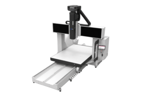
Today, a massive structural shift is taking place across the global manufacturing landscape. The rapid adoption of the industrial large format 3D printer is fundamentally changing how physical products are designed, prototyped, and produced. By expanding physical build envelopes up to several meters, these advanced systems allow modern creators to bypass traditional tooling, eliminate assembly bottlenecks, and print directly with high-strength composite polymers.
Whether your facility relies on high-capacity Fused Filament Fabrication (FFF) for ultra-precise geometries or cutting-edge Fused Granular Fabrication (FGF) pellet extrusion for rapid mass scale, investing in a large format 3D printer has evolved from an experimental luxury into an absolute competitive necessity for modern businesses.
The Industrial Maker Evolution: Breaking Free from Desktop Constraints
To appreciate why large format 3D printer technology is causing such a massive disruption today, it helps to understand where the maker movement ran into a wall. The early wave of 3D printing focused heavily on the desktop. Small, open-frame machines democratized access to slicing software and basic plastics like standard PLA. But while these early tools were excellent for minor visual models, small bracket prototyping, or hobbyist trinkets, they failed completely when subjected to true commercial, industrial, or architectural scaling.
The True Cost of Sliced and Fragmented Printing
When a design firm or engineering team attempts to build a large-scale structural part using a conventional desktop unit, they hit an immediate logistical bottleneck. Splitting a unified digital design into a matrix of smaller prints introduces severe operational risks:
-
Compromised Structural Integrity: Every single adhesive seam, solvent bond, or mechanical joint represents an acute point of failure. Under real-world mechanical loads, torsional stress, or ambient thermal fluctuations, these bonded seams are almost always the first areas to crack, shear, or delaminate.
-
Intensive Manual Labor Costs: Reassembling a multi-piece print requires countless hours of manual labor. Highly skilled technicians must spend their valuable time aligning seams, applying industrial adhesives, filling gaps with epoxy, sanding surfaces smooth, and applying structural coatings. This manual overhead drives up production costs and completely erases the speed advantages of additive manufacturing.
-
Dimensional Inaccuracy and Part Warpage: Different sections printed at different times—under varying ambient temperatures, humidity levels, or layer-cooling cycles—experience minor differences in thermal contraction. When you attempt to fit these pieces together, they rarely align perfectly, resulting in warped assemblies, out-of-tolerance parts, and expensive scrap material.
The Large-Format Breakthrough
Large-scale additive manufacturing completely rewrites this production playbook. By utilizing continuous build chambers that expand past a one-meter cube and stretch up to a massive $3500 \times 2400 \times 1000\text{ mm}$ volume, industrial makers can import a complex unibody design, press print, and walk away.
The completed component emerges from the machine as an integrated piece with consistent mechanical properties throughout its entire volume. This structural continuity allows the part to handle functional stresses, making it perfect for direct deployment on assembly lines, field testing, or end-use installations.
FFF vs. FGF: The Technical Systems Powering Large Scale
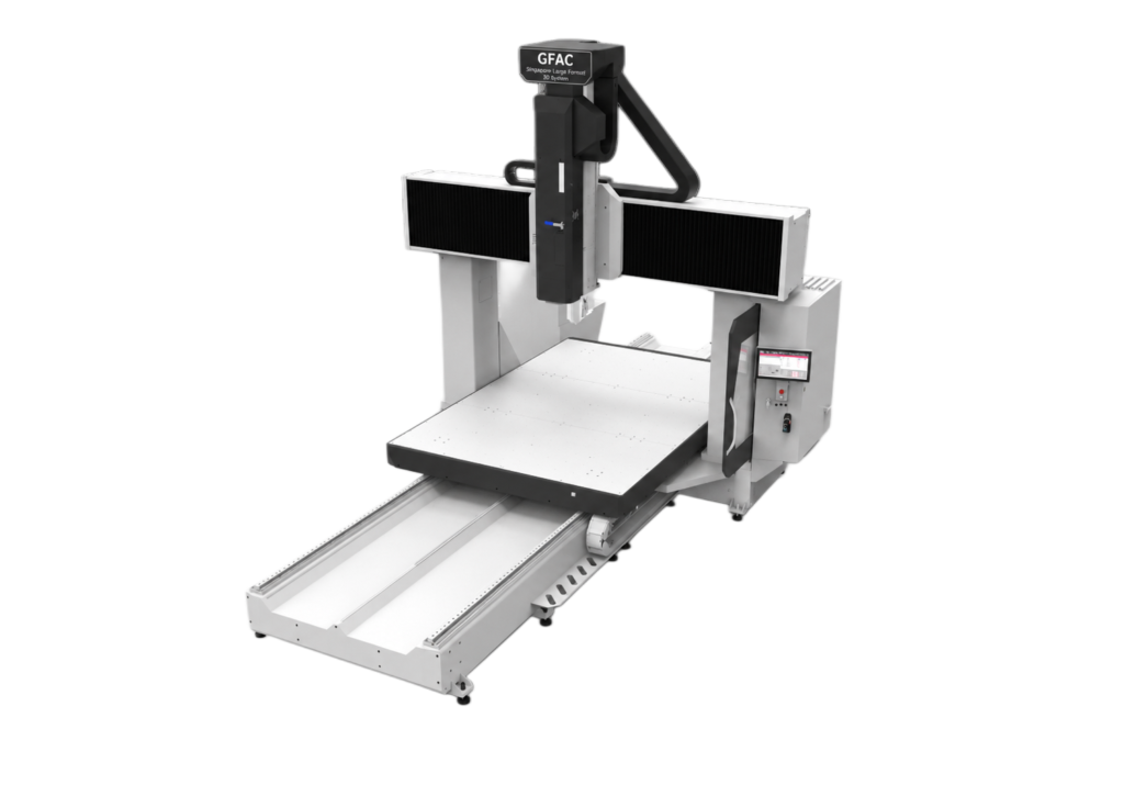
Selecting the right large format 3D printer architecture requires a deep understanding of the core extrusion technologies driving modern industrial machines. The market is divided into two major toolpaths: high-capacity Fused Filament Fabrication (FFF) and high-volume Fused Granular Fabrication (FGF). Both systems are engineered with industrial-grade closed-loop servo motors, heavy-duty linear guide rail modules, and multi-zone intelligent heating blocks to eliminate gantry vibration and ensure precision across immense footprints.
1. Advanced Industrial FFF (Fused Filament Fabrication)
Industrial FFF systems are the direct evolution of classic filament printing, scaled up and ruggedized for continuous, heavy-duty production cycles. These machines utilize thin, spooled plastic wires fed through a high-temperature print head.
To optimize material throughput across massive footprints, large-scale FFF units often move away from the standard 1.75mm line thickness found on desktop models. Instead, advanced configurations like the GFac GM1000 offer dedicated variants supporting 3.5mm filament lines.
By doubling the filament diameter, the system can deploy wider extrusion nozzle profiles (ranging from 0.8mm up to 2.0mm) to deposit material much faster, while maintaining precise control over intricate internal geometries and surface finishes.
-
Primary Advantages: Exceptional geometric fidelity, sharp crisp corners, highly precise dimensional tolerances, and the ability to print complex internal lattice structures or thin-walled enclosures with minimal post-processing.
-
To discover our full ecosystem of precision filament hardware, visit the GFac FFF Equipment Catalog.
2. High-Volume FGF (Fused Granular Fabrication) Pellet Extrusion
FGF technology represents the absolute frontier of heavy-duty industrial additive manufacturing. Instead of relying on expensive, pre-processed spooled filament, an FGF printer utilizes an internal screw extrusion mechanism fed directly by raw, industrial plastic pellets or granules.
The rotating internal compression screw grinds, compresses, and melts the raw pellets under high pressure and thermal energy inside the print head chamber. This design unlocks massive volumetric deposition rates.
While a high-performance FFF printer measures material throughput in grams per hour, a heavy industrial FGF system comfortably extrudes 1kg to 15kg of plastic material every single hour. Utilizing optional nozzle diameters stretching up to 16mm, FGF machines allow users to build ultra-large parts in hours rather than days.
-
Primary Advantages: Unmatched print speed, massive build capacities, excellent interlayer thermal adhesion due to the sheer mass of the deposited polymer, and incredible raw material cost savings.
-
Learn how pellet-extrusion can completely transform your manufacturing throughput via our GFac FGF Technology Guide.
The Economic Reality: How Large Format Systems Cut Costs by 80%
While the engineering advantages of a large format 3D printer are clear, the business decision to adopt this technology is ultimately driven by economics. In commercial manufacturing, product design, and heavy tooling industries, production speed and raw material expenditures dictate competitive survival.
The Raw Feedstock Price Gulf
When manufacturing parts that weigh 10kg, 50kg, or several hundred kilograms, the price per kilogram of your raw material becomes the dominant cost driver for the entire project. Standard 3D printing filaments undergo an intensive processing cycle: chemical manufacturers must take raw plastic resins, melt them, precisely extrude them into thin wires under strict laser-monitored tolerances, cool them, wind them onto spools, pack them with desiccant, and vacuum-seal them. Every step in this secondary processing pipeline adds a substantial financial premium.
Plastic pellets, by contrast, are the foundational raw material used across the global high-volume injection molding industry. They are manufactured worldwide by the millions of tons, completely bypassing the expensive secondary filament fabrication processes.
By switching massive production runs from a filament infrastructure to an industrial pellet-fed FGF system, businesses experience a 70% to 80% direct reduction in raw material costs. This cost efficiency makes large-scale additive manufacturing highly profitable for everyday commercial production.
-
Standard FFF Filament Spools: $25 to $60 per Kilogram average cost.
-
Industrial FGF Plastic Pellets: $3 to $12 per Kilogram average cost (Up to 80% savings).
Eliminating the Tooling Bottleneck
In traditional manufacturing setups, producing a large plastic or composite component requires creating an initial tool mold or die set. This process typically involves CNC-machining massive metal blocks or curing large epoxy blocks—a workflow that demands weeks of lead time and thousands of dollars in upfront capital investments before a single final part can be produced. If an engineering flaw or design mismatch is discovered during early field tests, the expensive tool mold must often be scrapped entirely, restarting the costly, time-consuming loop from scratch.
A large format 3D printer completely eliminates these upfront tooling barriers. A designer can easily modify a master CAD file, send it directly to a machine like the GFac JS-FGF-1200 or the ultra-large JS-FGF-3000, and begin printing a flawless, multi-meter functional prototype or end-use part within hours. Iteration happens dynamically in real-time, compressing product development cycles from months down to a few days.
Technical Specifications Matrix: GFac Equipment Lineup
To help factory managers, workshop directors, and lead engineers select the ideal hardware footprint for their operational needs, we have compiled the detailed mechanical, thermal, and dimensional specifications of GFac’s extensive hardware portfolio.
Industrial FGF Granular Series (Pellet-Fed Systems)
Engineered for continuous, high-volume industrial production, these heavy-duty systems feature advanced CNC control systems, automated pellet feeders, multi-zone intelligent heating blocks, and massive structural frames to eliminate harmonic vibrations.
| Equipment Model | Additive Molding Size (L × W × H mm) | Subtractive Milling Size (mm) | Nozzle Range | Heating Zones | Machine Weight | Power Requirements |
| JS-FGF-800Pro | $800 \times 600 \times 800$ | N/A | 0.4 – 2 mm | 2-Zone Intelligent | 350 kg | Single-phase AC 220V, 4.6kW |
| JS-FGF-1200 | $1200 \times 1000 \times 1000$ | N/A | 2 – 6 mm | 3-Zone Intelligent | 950 kg | Single-phase AC 220V, 6.0kW |
| JS-FGF-1800Pro | $1800 \times 1200 \times 1100$ | N/A | 2 – 6 mm | 3-Zone Intelligent | 1,300 kg | Single-phase AC 220V, 10.0kW |
| JS-FGF-AM-2420 | $2400 \times 2000 \times 1350$ | N/A | 3 – 12 mm | 4-Zone Intelligent | 6,000 kg | Three-phase AC 380V, 45.0kW |
| JS-FGF-HM-2435 | $3500 \times 2400 \times 1000$ | N/A | 3 – 16 mm | 4-Zone Intelligent | 11,000 kg | Three-phase AC 380V, 70.0kW |
| JS-FGF-3000 | $3000 \times 2000 \times 1000$ | N/A | 2 – 6 mm | 3-Zone Intelligent | 6,000 kg | Three-phase AC 380V, Dual-Feed |
| JS-FGF-HM-3000 | $3000 \times 2000 \times 1000$ | $3000 \times 2000 \times 1000$ | 4 – 12 mm | 4-Zone Intelligent | 16,000 kg | Three-phase AC 380V, Hybrid |
To evaluate specific mechanical dimensions and layout guidelines for your facility floor, view the GFac Product Overview Hub.
High-Precision FFF Filament Series
Optimized for precise geometric fidelity, closed-loop servo control, automated bed leveling calibration, power-off resume functionality, and seamless handling of technical engineering materials.
| Equipment Model | Molding Size (L × W × H mm) | Gross Weight | Filament Diameter | Max Nozzle Temp | Printing Speed Range | Motor Configuration |
| GM1000 (1.75mm) | $1000 \times 1000 \times 1000$ | >550 kg | 1.75 mm | 310°C | 30 – 350 mm/s | Closed-loop servo, 4-axis screw |
| GM1000 (3.5mm) | $1000 \times 1000 \times 1000$ | 550 kg | 3.5 mm | 310°C | 30 – 350 mm/s | Closed-loop servo, 4-axis screw |
| G610 | $600 \times 600 \times 1000$ | >450 kg | 1.75 mm | 320°C | 30 – 300 mm/s | Industrial closed-loop servo |
| G500pro | $500 \times 500 \times 600$ | >130 kg | 1.75 mm | 320°C | 30 – 500 mm/s | Industrial closed-loop servo |
| G300pro | $300 \times 300 \times 400$ | >48 kg | 1.75 mm | 320°C | 30 – 500 mm/s | Industrial closed-loop servo |
| G500 | $400 \times 400 \times 500$ | 70 kg | 1.75 mm | 320°C | 30 – 500 mm/s | Heavy-duty stepper configuration |
| G300 | $300 \times 300 \times 400$ | >50 kg | 1.75 mm | 320°C | 30 – 500 mm/s | Heavy-duty stepper configuration |
| G220 | $220 \times 220 \times 250$ | >25 kg | 1.75 mm | 320°C | 30 – 500 mm/s | Entry-level stepper configuration |
Material Science: Advanced Composites That Replace Metals
Modern large format 3D printer technology has completely outgrown basic, brittle plastics. Today’s industrial makers have access to advanced engineering polymers and composite resins reinforced with microscopic fibers, yielding parts that can confidently replace structural metal alloys.
1. Standard Commodity Polymers
Materials like basic PLA, ABS, and PETG serve well for quick visual prototypes, low-stress workshop fixtures, and everyday anatomical or geometric models where extreme mechanical stress isn’t an issue.
2. Reinforced Structural Composites
By blending raw polymers with microscopic carbon fibers or glass fibers, material scientists have unlocked physical properties suited for demanding mechanical conditions:
-
PC+CF (Polycarbonate + Carbon Fiber): Delivers incredible structural stiffness, high impact resistance, and an exceptionally low coefficient of thermal expansion. This material is widely used for manufacturing industrial vacuum-forming molds, high-pressure alignment fixtures, and lightweight automotive brackets.
-
PA+GF (Polyamide/Nylon + Glass Fiber): Offers superior heat deflection profiles and mechanical toughness. This composite retains its structural integrity in abrasive environments and high-heat conditions, such as automotive engine bays.
-
PP+GF (Polypropylene + Glass Fiber): Combines strong chemical resistance with excellent moisture defense, making it a go-to material for chemical piping components, fluid tanks, and maritime prototyping.
3. High-Performance Ultra Resins
For elite aerospace or chemical engineering applications, specialized high-end polymers offer extreme thermal thresholds and chemical limits:
-
PESU+CF & PPS+CF Pellets: High-performance engineering composites capable of withstanding continuous operating temperatures well above 200°C while resisting aggressive industrial solvents, chemical washes, and automotive fluids.
-
TPU (Thermoplastic Polyurethane): Opens up large-scale flexible manufacturing. Ideal for printing oversized industrial gaskets, custom footwear components, vibration-dampening structures, and impact-resistant protective bumpers.
To download exact material data sheets, mechanical compounding guides, and safety profiles, browse our material directories:
Real-World Applications Across Core Industries
The deployment of a heavy-duty large format 3D printer yields massive efficiency gains across multiple multi-billion dollar industrial sectors throughout the Asia-Pacific region.
1. Automotive and Aerospace Production
In automotive manufacturing, long development cycles for custom panels and assembly tooling disappear. Engineers use systems like the JS-FGF-AM-2420 to print full-scale bumper prototypes, structural aerodynamic components, and custom assembly jigs right on the factory floor.
Aerospace firms utilize high-temperature platforms to produce ultra-lightweight interior brackets, functional ducting, and carbon-fiber layup molds capable of surviving pressurized autoclave cycles.
2. Heavy Industrial Molds, Casting, and Dies
Foundries and mold-making facilities are experiencing a complete workflow revolution by adopting advanced hybrid additive systems like the JS-FGF-HM-3000. This massive 16-ton machine combines high-volume additive pellet 3D printing with subtractive CNC milling on a single gantry platform.
The process functions across two clear phases:
-
Phase 1 (Additive Print): The high-output FGF head rapidly deposits raw pellet composite materials to build a near-net shape slightly oversized.
-
Phase 2 (Subtractive Mill): The integrated high-speed CNC milling spindle moves along the exact same gantry, shaving the printed part down to micro-level engineering tolerances.
Instead of waiting months for a metal casting tool to be carved, this hybrid approach reduces tool creation lead times from months to mere days.
3. Architecture, Sculpture, and Experiential Exhibits
Architectural firms utilize large format systems to manufacture highly intricate, irregular curtain walls, custom building facade mockups, and complex concrete casting formwork that would be cost-prohibitive to build conventionally.
At the same time, artistic fabrication studios and experiential branding agencies use these massive build volumes to create lightweight, unibody public sculptures, custom organic furniture installations, and eye-catching event props without the weakness of glued seams.
Step-by-Step Guide to Successful Large-Format Printing
Successfully executing a multi-day print that consumes tens of kilograms of material requires precise process engineering. Follow this structured checklist to ensure a perfect first-time yield on your industrial platform:
Step 1: Design Optimization for Additive Mass
When designing large-scale components in CAD, completely avoid sharp, un-filleted 90-degree internal corners, especially near the base layer. Sharp corners concentrate thermal stresses as the plastic cools down, which causes the part to lift and warp off the bed. Always apply generous fillets and chamfers to distribute internal cooling stresses evenly.
Step 2: Feedstock Preparation and Moisture Control
Industrial polymers—especially hydroscopic materials like Nylon (PA) or Polycarbonate (PC)—absorb ambient moisture from the air. If damp pellets or filament enter the extruder, the moisture instantly vaporizes into steam bubbles, causing structural voids, weak layer bonding, and poor surface finishes. Always pass your raw feedstock through an integrated drying system prior to printing.
Step 3: Slicer Optimization and Infill Engineering
Import your CAD design into your slicing software and select your nozzle variables. For ultra-fast FGF pellet prints using a 4mm nozzle, configure layer heights between 1.5mm and 2.0mm. Utilize specialized 3D infill geometries like the Gyroid or Cross-3D pattern. These shapes provide uniform multi-directional strength while minimizing excess plastic mass that traps heat.
Step 4: Active Thermal Chamber Management
Maintain a stable, warm temperature inside your printer’s enclosed chamber throughout the entire print cycle. This prevents the deposited plastic layers from cooling down too quickly, ensuring optimal molecular cross-linking between layers and completely eliminating delamination risks. Once the print finishes, allow the machine to cool down slowly to room temperature before removing the finished part from the build plate.
Frequently Asked Questions (FAQ)
What dimensions qualify a 3D printer as “large format”?
A 3D printer is widely classified as large format when its build envelope exceeds a $500 \times 500 \times 500\text{ mm}$ footprint. Highly advanced industrial configurations can comfortably reach a 1-meter cube volume or expand up to a massive $3500 \times 2400 \times 1000\text{ mm}$ workspace.
Why should my factory choose an FGF pellet system over an FFF filament printer?
FGF pellet systems provide two critical advantages for large-scale operations: up to 80% lower raw material costs and significantly faster deposition speeds. FGF systems use high-pressure internal screws to extrude kilograms of plastic per hour, making them ideal for massive parts, while FFF filament systems are better for parts that require intricate cosmetic details.
How do large-scale 3D printers eliminate warping and layer splitting?
Warping is caused by plastic contracting as it cools down. Industrial large format systems solve this by utilizing fully sealed, insulated thermal chambers, multi-zone intelligent heating beds, and advanced composite feedstocks (such as carbon fiber or glass fiber filled resins) that possess exceptionally low thermal expansion profiles.
What exactly is an additive + subtractive hybrid 3D printer?
A hybrid printing system, such as the GFac JS-FGF-HM-3000, mounts both a high-volume pellet extrusion print head and a high-precision subtractive CNC milling spindle on the exact same robotic gantry. The machine rapidly prints the near-net shape of an object and immediately mills it down to a mirror-smooth finish with micrometer precision within a single automated print cycle.
Where can I purchase an industrial large format 3D printer in Singapore?
G Factor (GFac) is Singapore’s premier manufacturer of industrial large format 3D printing equipment. We design, manufacture, and customize advanced FFF and FGF systems directly from our corporate headquarters in Singapore, providing end-to-end technical training, maintenance, and material compounding services across the Asia-Pacific region.
Summary: Embracing the Big Additive Frontier
The desktop printing wave altered how the world approaches early-stage visual prototyping; the large format 3D printer revolution is fundamentally transforming the reality of industrial manufacturing. By removing the mechanical weaknesses of multi-part assemblies, crashing raw material expenses by utilizing direct-injection molding pellets, and introducing composite engineering feedstocks, these heavy-duty systems empower makers to build without boundaries.
Integrating a large format platform into your facility slashes product development cycles from months to days, eliminates expensive upfront tooling investments, and gives your business a massive competitive advantage.
Ready to Scale Up Your Production Footprint?
At G Factor (GFac), we build industry-leading large-scale FFF and FGF systems engineered specifically to deliver cost efficiency plus fast and stable production yields. Whether your operation requires a high-precision, high-temperature FFF unit for intricate aerospace parts or a massive 16-ton hybrid additive+subtractive system for heavy industrial mold production, our Singapore-based engineering team provides the perfect solution.
-
Review Hardware Specs: Explore our entire lineup of industrial systems on the GFac Product Overview Hub.
-
Request an Engineering Consultation: Ready for a customized machine quote, a material capability discussion, or a facility demo? Connect directly with our technical business advisors via the GFac Contact & Consultation Portal. Let’s build the future together.